V9000 Series Bellows Control Valve

VMV V9000 series GLOBE straight-stroke bellows control valve is developed by Newton’s professional R&D team. Conventional control valve, packing is easy to wear, leak externally, poor adjustment regulating, bellows seal is not durable and other phenomena.

Description

VMV V9000 series GLOBE straight-stroke bellows control valve is developed by Newton’s professional R&D team. In view of the conventional control valve, packing is easy to wear, leak externally, poor adjustment regulating, bellows seal is not durable and other phenomena, VMV has collected much operational condition informatio and researched technically for the above phenomenon.Many tests have proved that the V9000 series can fully meet the users’ needs, especially applied in the petrochemical industry and high requirements for fresh air and other special conditions.

  • Long-term operation, maintenance-free to keep working
  • Zero leakage of valve stem during long operation cycles
  • Bellows’ operational service life >500,000 times
  • High regulating precision
  • Fast response speed
  • Convenient and quick on-site valve maintenance
  • Wide temperature range(-196℃~588℃)

VMV equipped with either pneumatic diaphragm actuator or electric actuator according to the user’s on-site energy

Nominal diameter DN15(NPS1/2)~DN300
Pressure rating PN16~PN420、Class150~Class2500
Operating voltage (electric actuator) 220VAC, 380VAC, 24VDC
Air supply pressure (pneumatic actuator) 0.4~0.6MPa
Operating temperature -45~588 ℃
Packing V-type combination packing(≤300℃)
Graphite combination packing(>300℃)
Rated Cv value See table below
Flow characteristic Equal percentage, linear, quick opening
Regulating 50:1
Leakage level IV (metal hard seal)
V (metal hard seal)
VI (soft seal)
Hysteresis <1%
Dead zone <0.8%
Allowable differential pressure See table below
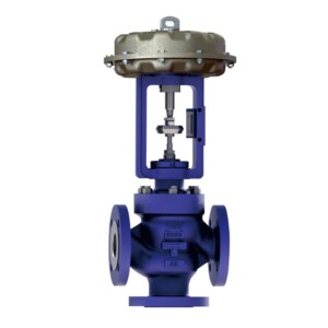
5.1 Single-seat control valve

V9000 SERIES BELLOWS CONTROL VALVE Structure And Characteris1

①. Bellows anti-rotation Structure
The keyway on the valve stem is matched with the pin of the bellows sleeve. Forcing the bellows to move along the axis to prevent damage and increase the service life of the bellows.

②. Bellows failure detection structure
A pressure gauge or pressure sensor can be connected to the detection port on the valve bonnet for real-time monitoring of bellows leakage.

③. Single bonnet structure
Lower external leakage risk.

④. Thread + Pin Connection Structure
The plug and stem are closely connected, and there is no relative moving gap. Effectively prevent stem fatigue and fracture caused by the relative swing of the plug and stem.

⑤. Sealing gasket quantitative compression structure
Prevent the gasket from being overly compressed to achieve durable sealing without leakage.

⑥. Up-pressure valve seat structure
By loosening the valve bonnet bolts, the internal components of the valve can be removed one by one, allowing for quick maintenance and replacement of the valve seat and internal components on-site,thus saving the user’s maintenance time.

⑦. Bellows and flow channel separation structure
Prevent the medium from directly impacting the bellows, improve the service life of the bellows.

⑧. Double-guided valve plug structure
The valve core operates smoothly, not prone to vibration and sticking,ensuring higher regulating precision.cc

⑨. Bellows structure with protective armor
Protects the bellows during handling, installation, and operation. Without bonnet parts, more convenient and fast to replace.

⑩. Bellows external pressure bearing structure
Provide stable pressure load for bellows, reduce movement and increase the maximum allowable stress, thus improving the bellows service life and valve operation accuracy.

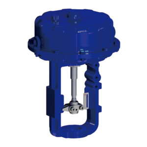
5.2 Balanced Single-Seat Bellows Control Valve

V9000 SERIES BELLOWS CONTROL VALVE Structure And Characteris2

①. Wear-resistant piston ring seal structure
The wear-resistant piston ring still has self-lubricating at temperatures above 200°C, making the valve not easy to stretch and stick during the long period regulating process, maintaining a seal class above level IV .

②. Balanced single-seat structure
Low thrust overcomes the large pressure difference, has better performance of overcoming differential pressure.

③. Spherical valve plug structure
The throttling orifice is uniformly distributed on the surface of the valve core, allowing the medium to flow smoothly and stably, thus has higher regulating precision.

6.1 Common valve trim materials
Body Seat Plug Stem Bellows Packing
JS1249 420+HT 420+HT 410 304 PTFE
WCB 304+STL 304+STL 630 316 Flexible graphite
LCB 304 304 XM-19 HC276
WC6 316L+STL 316L+STL 304 316Ti
WC9 321+STL 321+STL 316L
CFS 304+RPTFE 304+RPTFE HC276
CF3 316L+RPTFE 316L+RPTFE
CF8M Fll+Q.STL Fll+Q.STL
CF3M HC276 HC276
HC276
6.2 Temperature and pressure corresponding range of valve body material(MPa)
Temp Class150 Class300 Class600
WCB WC6 WC9 CF8 CF8M WCB WC6 WC9 CFS CF8M WCB WC6 WC9 CF8 CF8M
-196~-30 1.90 1.90 4.96 4.96 9.93 9.93
-29~38 1.96 1.98 1.98 1.90 1.90 5.11 5.17 5.17 4.96 4.96 10.21 10.34 10.34 9.93 9.93
50 1.92 1.95 1.95 1.83 1.84 5.01 5.17 5.17 4.78 4.81 10.2 10.34 10.34 9.56 9.62
100 1.77 1.77 1.77 1.57 1.62 4.66 5.15 5.15 4.09 4.22 9.32 10.3 10.3 8.17 8.44
150 1.58 1.58 1.58 1.42 1.48 4.51 4.97 5.03 3.7 3.85 9.02 9.95 10.03 7.4 7.7
200 1.38 1.38 1.38 1.32 1.37 4.38 4.8 4.86 3.45 3.57 8.76 9.59 9.72 6.9 7.13
250 1.21 1.21 1.21 1.21 1.21 4.19 4.63 4.63 3.25 3.34 8.39 9.27 9.27 6.5 6.68
300 1.02 1.02 1.02 1.02 1.02 3.98 4.29 4.29 3.09 3.16 7.96 8.57 8.57 6.18 6.32
325 0.93 0.93 0.93 0.93 0.93 3.87 4.14 4.14 3.02 3.09 7.74 8.26 8.26 6.04 6.18
350 0.84 0.84 0.84 0.84 0.84 3.76 4.03 4.03 2.96 3.03 7.51 8.04 8.04 5.93 6.07
375 0.74 0.74 0.74 0.74 0.74 3.64 3.89 3.89 2.9 2.99 7.27 7.76 7.76 5.81 5.98
400 0.65 0.65 0.65 0.65 0.65 3.47 3.65 3.65 2.84 2.94 6.94 7.33 7.33 5.69 5.89
425 0.55 0.55 0.55 0.55 0.55 2.88 3.52 3.52 2.8 2.91 5.75 7.00 7.00 5.6 5.83
450 0.46 0.46 0.46 0.46 3.37 3.37 2.74 2.88 6.77 6.77 5.48 5.77
475 0.37 0.37 0.37 0.37 3.17 3.17 2.69 2.87 6.34 6.34 5.39 5.73
500 0.28 0.28 0.28 0.28 2.57 2.82 2.65 2.82 5.15 5.65 5.3 5.65
538 0.14 0.14 0.14 0.14 1.49 1.84 2.44 2.52 2.98 3.69 4.89 5.00
550 1.27 1.56 2.54 3.13
575 0.88 1.05 1.76 2.11
600 0.61 0.69 1.22 1.38
Temp℃ PN16 PN25 PN40
WCB WC6 WC9 CF8 CF8M WCB WC6 WC9 CFS CF8M WCB WC6 WC9 CF8 CF8M
-196~-30 1.57 1.57 2.45 2.45 3.92 3.92
-29~38 1.61 1.63 1.63 1.57 1.57 2.52 2.55 2.55 2.45 2.45 4.03 4.08 4.08 3.92 3.92
50 1.58 1.63 1.63 1.51 1.52 2.47 2.55 2.55 2.36 2.37 3.95 4.08 4.08 3.78 3.8
100 1.46 1.63 1.63 1.29 1.33 2.29 2.54 2.54 2.02 2.08 3.66 4.06 4.07 3.23 3.33
150 1.43 1.57 1.58 1.17 1.22 2.23 2.45 2.48 1.83 1.9 3.57 3.93 3.96 2.93 3.04
200 1.38 1.51 1.54 1.09 1.13 2.16 2.37 2.41 1.7 1.76 3.46 3.79 3.85 2.72 2.82
250 1.32 1.46 1.46 1.03 1.05 2.06 2.28 2.29 1.6 1.65 3.29 3.64 3.66 2.56 2.63
300 1.22 1.35 1.35 0.97 1 1.91 2.11 2.11 1.51 1.56 3.06 3.38 3.38 2.42 2.5
350 1.17 1.27 1.27 0.93 0.96 1.82 1.98 1.98 1.46 1.5 2.9 3.18 3.18 2.33 2.4
375 1.15 1.23 1.23 0.92 0.94 1.8 1.91 1.91 1.44 1.47 2.88 3.06 3.06 2.3 2.36
400 1.09 1.15 1.15 0.9 0.93 1.7 1.8 1.8 1.41 1.45 2.72 2.89 2.89 2.26 2.32
425 0.91 1.11 1.11 0.88 0.92 1.42 1.73 1.73 1.37 1.44 2.27 2.77 2.77 2.2 2.3
450 1.07 1.07 0.86 0.91 1.67 1.67 1.35 1.42 2.67 2.67 2.16 2.28
475 1 1 0.85 0.91 1.56 1.56 1.33 1.41 2.5 2.5 2.13 2.26
500 0.8 0.88 0.84 0.86 1.24 1.37 1.31 1.35 1.99 2.19 2.09 2.16
525 0.57 0.68 0.76 0.8 0.9 1.07 1.19 1.25 1.43 1.71 1.9 2
550 0.4 0.49 0.69 0.76 0.63 0.76 1.07 1.18 1 1.21 1.72 1.89
575 0.28 0.33 0.63 0.43 0.52 0.99 0.69 0.83 1.58
600 0.19 0.22 0.53 0.3 0.31 0.83 0.48 0.51 1.32
Temp PN63 PN100
WCB WC6 WC9 CF8 CF8M WCB WC6 WC9 CF8 CF8M
-196~-30 6.17 6.17 9.8 9.8
-29~38 6.35 6.43 6.43 6.17 6.17 10.08 10.21 10.21 9.8 9.8
50 6.22 6.43 6.43 5.95 5.98 9.88 10.21 10.21 9.44 9.5
100 5.77 6.4 6.41 5.08 5.25 9.15 10.16 10.17 8.07 8.33
150 5.62 6.19 6.24 4.62 4.79 8.92 9.82 9.9 7.34 7.6
200 5.45 5.96 6.06 4.29 4.43 8.65 9.47 9.63 6.81 7.04
250 5.19 5.74 5.76 4.04 4.15 8.23 9.11 9.14 6.41 6.59
300 4.81 5.33 5.33 3.81 3.93 7.64 8.46 8.16 6.05 6.24
350 4.59 5 5 3.67 3.79 7.29 7.94 7.94 5.83 6.01
375 4.53 4.82 4.82 3.63 3.72 7.2 7.66 7.66 5.76 5.9
400 4.29 4.55 4.55 3.56 3.66 6.81 7.22 7.22 5.64 5.81
425 3.57 4.36 4.36 3.46 3.62 5.67 6.92 6.92 5.5 5.75
450 4.2 4.2 3.4 3.59 6.67 6.67 5.4 5.69
475 3.94 3.94 3.35 3.56 6.25 6.25 5.32 5.66
500 3.14 3.46 3.29 3.4 4.98 5.49 5.23 5.4
525 2.26 2.69 2.99 3.14 3.58 4.28 4.75 4.99
550 1.58 1.91 2.7 2.97 2.51 3.03 4.29 4.72
575 1.09 1.31 2.5 1.74 2.08 3.96
600 0.75 0.86 2.08 1.19 1.36 3.31
6.3 The valve trim material corresponds to the temperature and pressure range

①Valve plug (valve seat) material 420+HT
V9000 ①Valve plug (valve seat) material 420+HT

② Valve plug (valve seat) material: F11+Q.STL

V9000 ②Valve plug (valve seat) material F11+Q.STL

③ Valve plug (valve seat) material: 304+STL/316L+STL

V9000 ③Valve plug (valve seat) material 304+STL 316L+STL

④ Valve plug (valve seat) material: 304/316L

V9000 ④Valve plug (valve seat) material 304 316L

⑤ Valve plug material: 304+RPTFE/316L+RPTFE

V9000 ⑤Valve plug material 304+RPTFE 316L+RPTFE

⑥ Packing material: PTFE

V9000 ⑥Packing material PTFE

⑦ Packing material: graphite

V9000 ⑦Packing material graphite

V9000 7.Typical flow characterissc curve

Nominal diameter Travel Valve seat diameter code Rated CV
Linear Equal percentage
16 6E 0.002
16 6D 0.005
16 6C 0.008
16 6B 0.01
16 6A 0.08
16 6 0.12 0.12
16 7 0.23 0.23
16 8 0.58 0.58
16 10 1.2 1.2
16 12 1.9 1.9
16 14 2.9 2.9
DN15 16 15 4.7 4.7
16 18 7.4 7.4
DN20 16 20 10 10
DN25 16 25 14 14
DN32 20 32 24 24
DN40 20 40 30 30
DN50 20 50 48 45
DN65 30 65 74 74
DN80 30 80 117 117
DN100 30 100 187 187
DN125 60 125 320 287
DN150 60 150 456 433
DN200 60 200 749 678
DN250 10 250 1100 950
DN300 10 300 1600 1400
DN350 130 350 2100 1900
DN400 130 400 2800 2600
Nominal diameter Actuator model PN lOMPa (metal seal level IV )
PTFE packing Graphite packing
Unbalanced single seat structure Balanced single seat structure Unbalanced single seat structure Balanced single seat structure
DN20 MT1 4.3 1.9
DN25 MT1 3.6 1.6
DN32 MT1 1.9 6 0.9 2.2
DN40 MT1 1.3 6 0.7 2.2
DN50 MT1 0.8 6 0.4 2.2
DN65 MT2 1.2 8.7 1.1 5
DN80 MT2 0.8 8.7 0.7 6.5
DN100 MT2 0.5 6.8 0.4 5
DN125 MT3 0.7 10 0.2 9.2
DN150 MT3 0.5 9.8 7.7
DN200 MT3 6 4.6
DN250 MT4 7.2 5.6
DN300 MT4 5.7 4.5

V9000 SERIES BELLOWS CONTROL VALVE Dimensions and Weight

10.1 Overall dimensions (mm)
Nominal diameter Actuator model L H1 H2 H3 ΦA
PN16 PN25 PN40 CLASS 150 CLASS 300 PN63 PN100 CLASS600 Standard type bonnet Radiator fin type bonnet Without handwheel With handwheel
DN15 MT1 160 160 160 160 194 206 75 310 425 300 450 180
DN20 MT1 160 160 160 160 194 206 75 310 425 300 450 180
DN25 MT1 160 160 160 160 197 210 75 310 425 300 450 180
DN32 MT1 180 180 180 180 222 251 90 335 455 300 450 180
DN40 MT1 200 200 200 200 235 251 90 335 455 300 450 180
DN50 MT1 230 230 230 230 267 286 105 375 495 300 450 180
DN65 MT2 290 290 290 290 292 311 115 454 654 398 651 270
DN80 MT2 310 310 310 310 318 337 120 454 654 398 651 270
DN100 MT2 350 350 350 350 368 394 145 479 689 398 651 270
DN125 MT3 400 400 400 400 425 457 189 780 1100 681 890 400
DN150 MT3 480 480 480 480 473 508 189 780 1100 681 890 400
DN200 MT3 600 600 600 600 568 610 239 801 1150 681 890 400
DN250 MT4 673 708 708 673 708 752 305 1129 1500 1100 1700 590
DN300 MT4 737 775 775 737 775 819 335 1294 1650 1100 1700 590
10.2 Weight (kg)
Nominal Diameter Actuator model Weight
PN≤5MPa PN≤10MPa
Without handwheel With handwheel Without handwheel With handwheel
DN15 MT1 17 24 20 27
DN20 MT1 17 24 20 27
DN25 MT1 17 24 20 27
DN32 MT1 33 40 41 48
DN40 MT1 34 41 42 49
DN50 MT1 35 42 43 50
DN65 MT2 65 75 79 89
DN80 MT2 67 77 82 92
DN100 MT2 86 96 106 116
DN125 MT3 171 190 209 228
DN150 MT3 202 221 249 268
DN200 MT3 285 304 357 376
DN250 MT4 531 566 662 697
DN300 MT4 703 738 885 920

11.Valve Body Casting Material Comparison Table


ASTM DIN EN JIS
A216 WCB 1.0619 GS-C25 G5151 SCPH2
A536 60-40-80 Js1049 GGG40 G5502 FCD400-15
A352 LCB 1.1131 G17Mn5 G5152 SCPL1
A217 WC6 1.7357 G17CrMo5-5 G5151SCPH21
A217 WC9 1.7379 G17CrMo9-10 G5151 SCPH-32
A351 CF8 1.4308 GX5CrNi19-10 G5151SCS13A
A351 CF3 1.4309 GX2CrNi19-11 G5151SCS19A
A351 CF8M 1.4408 GX5CrNiMo19-11-2 G5151SCS14A
A351 CF3M 1.4409 GX2CrNiMo19-11-2 G5151SCS16A
A351 CF8C 1.4552 GX5CrNiNb19-11 G5151 SCS21

Please fill in your email address to obtain the password to view VR permissions.
We will contact you within 24 hours. Thank you.


True Efficiency Use VMV

What can we do for you?
 
1. 26 years of brand history and industry experience.
2. Complete certificates, first-class standard.
3. Stable and high level product quality.
4. Regular products, delivery within 7 days.
5. Price support, adapt to the local market.
6. Team of 37 engineers, reliable technical support.
7. Professional training, online and offline form.
8. VR live display, not limited by geography.
9. Sale and service, 12 hours quick response.
etc…

Talk with us