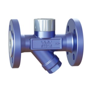
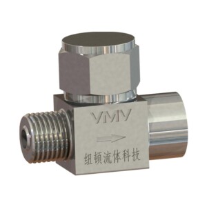
QYL Automatic Level Control Device for Vapour-Liquid Two-Phase Flow Trap

After the drainage flows through the specially designed front-end valve core and is blocked, it enters the valve chamber. The liquid level in the container slowly rises to the interface of the phase change tube, and the phase change tube changes from a vapor phase signal to a liquid phase signal.

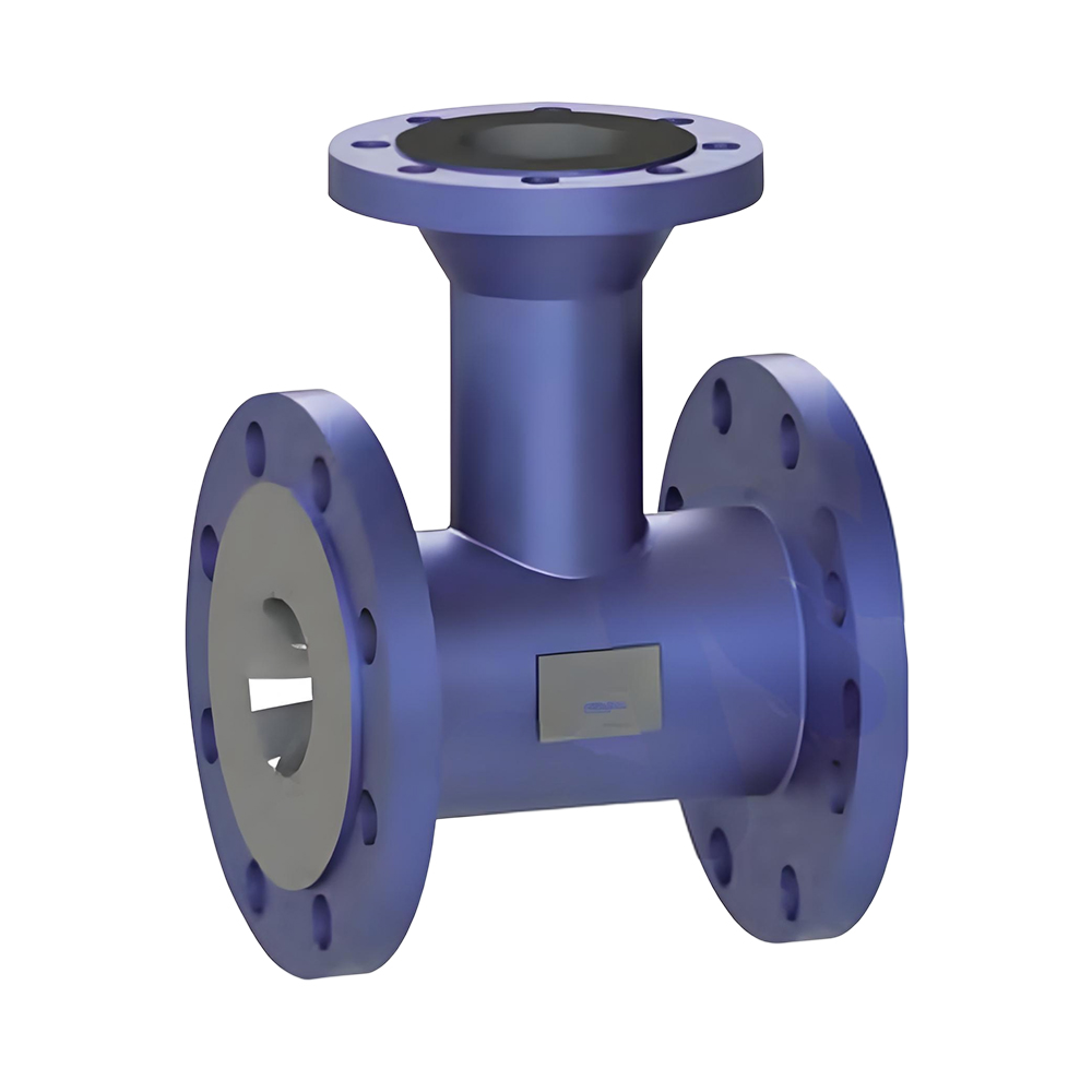
QYL Automatic Level Control Device for Vapour-Liquid Two-Phase Flow Trap

Description

Working Principle

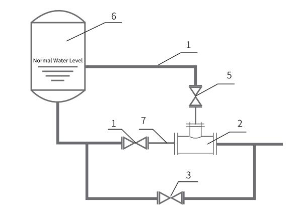
After the drainage flows through the specially designed front-end valve core and is blocked, it enters the valve chamber. The liquid level in the container slowly rises to the interface of the phase change tube, and the phase change tube changes from a vapor phase signal to a liquid phase signal. At this time, the front end drainage and liquid phase pipe drainage mix and flow towards the designated rear end throat. Due to the unchanged throat area setting, the maximum drainage displacement occurs when the liquid level rises to the required normal water level (the rear valve core is the control expansion end); When the liquid level decreases, the steam consumption signal increases and enters the regulator, reducing the effective flow area of the throat drainage and the drainage discharge, thereby achieving the purpose of controling
the water level.

Features
  • Phase change tube (signal tube): To collect vapor and liquid phase signals based on the liquid level.
  • Self regulating liquid level controller: The main equipment for controlling the liquid level.
  • Bypass valve: A gate valve that corrects errors caused by inaccurate parameter provision.
  • Inlet valve: A gate valve.
  • Steam valve: A gate valve.
  • Heater
  • Connection short pipe

llustration
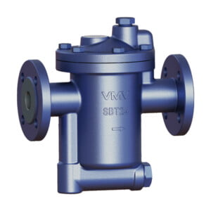
qyl illustrision


Technical Parameters
Nominal pressure PN40
Max. allowable pressure (Shell) 3.92MPa/200℃
Max. allowable temperature (Shell) 450℃/1.66MPa
Factory steam action test >3 times/1.6MPa
Max. working pressure 3.2MPa
Max. operating temperature 350℃
Factory cold test pressure 6.0MPa
Air test 2.0MPa

Body: A105/SS
Seat: 420

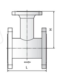
qyl structure diagram

unit (mm)

Model Size L H
QYL-16

PN16

65-50 235 205
80-50 255 210
100-50 265 225
125-50 265 265
150-80 265 265
200-80 297 310
QYL-40

PN40

80-50 327 240
100-50 269 287
125-50 260 245
150-80 364 305

Please fill in your email address to obtain the password to view VR permissions.
We will contact you within 24 hours. Thank you.


True Efficiency Use VMV

What can we do for you?
 
1. 26 years of brand history and industry experience.
2. Complete certificates, first-class standard.
3. Stable and high level product quality.
4. Regular products, delivery within 7 days.
5. Price support, adapt to the local market.
6. Team of 37 engineers, reliable technical support.
7. Professional training, online and offline form.
8. VR live display, not limited by geography.
9. Sale and service, 12 hours quick response.
etc…

Talk with us