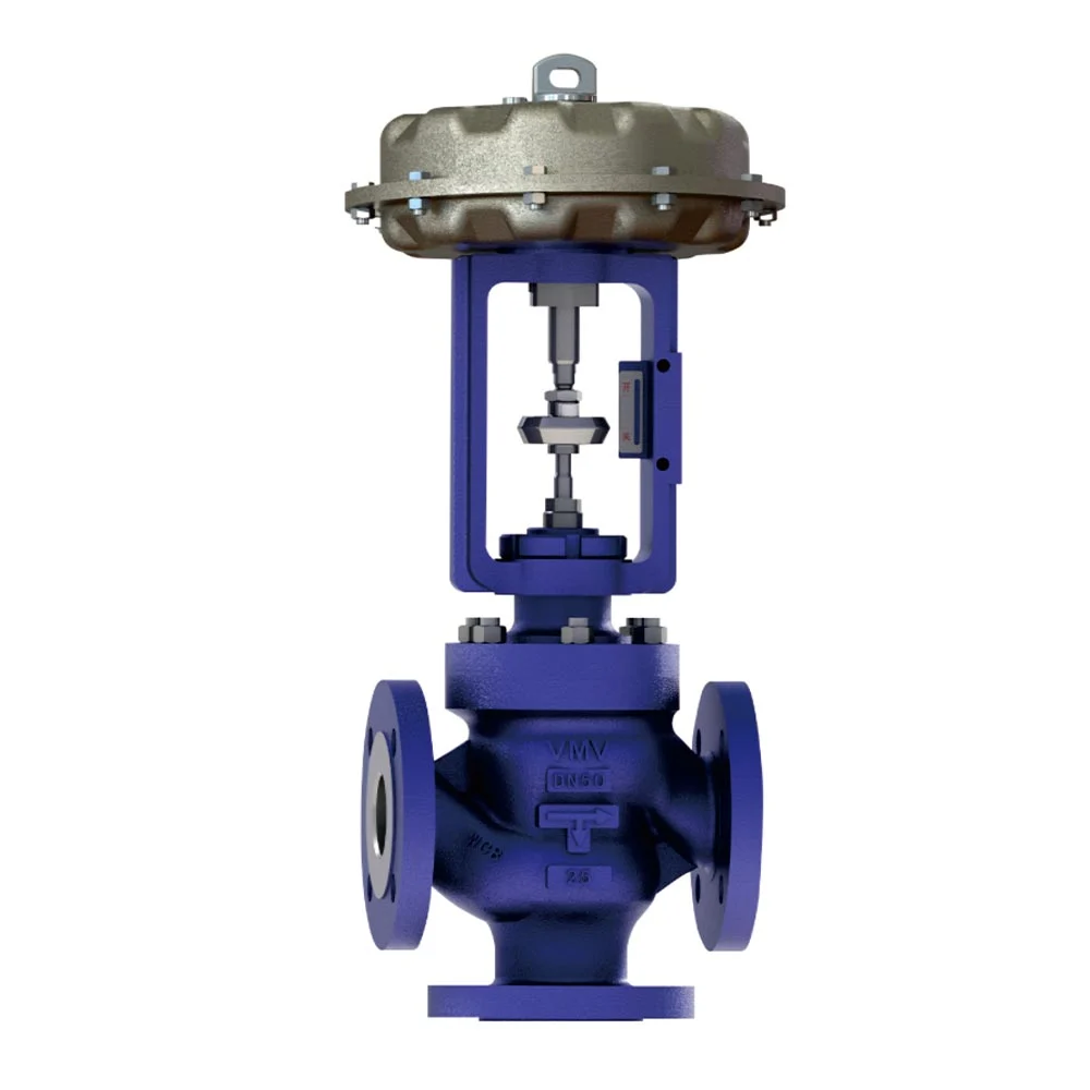
In the heating industry, a three-way control valve is a common fluid control component, often used to precisely control process parameters of media such as gas, liquid, and steam. It can replace two two-way control valves to regulate temperature and flow. Structurally, it typically consists of an actuator (such as a pneumatic diaphragm or electric actuator) and a three-way valve body, which features a cylindrical, thin-walled window valve core. It is widely used in heat exchanger temperature control and fluid proportioning systems in the petroleum, chemical, and power industries.
Working Principle
The operating principle of a three-way control valve can be summarized as follows: The actuator drives the valve core/seat and other internal components to change the connection between the three flow ports (inlet A, outlet B, and reversing port C), thereby achieving precise control of the flow direction and flow rate of the media. The specific working process is as follows:
1. Valve Core Position Changes Flow Connection
When the actuator (such as a pneumatic actuator, electric actuator, or manual handwheel) is actuated, the valve core moves within the valve body, connecting inlet A with outlet B or reversing port C, or simultaneously closing/opening different channels. For example, when the valve core is in the lower position, both the left and right ports are open. When the valve core is in the upper position, the left and lower ports are open, and the right port is blocked.
2. Controlling Media Flow Direction and Flow
Depending on their function, three-way control valves can be divided into converging and diverting types. Converging: Two media flow into two inlets merge and flow out through a single outlet. Diverting: One media flow into one inlet is divided into two and flows out through two outlets.
By synchronously adjusting the valve core opening, flow can be distributed between different branches in real time. For example, in a thermal oil system, the ratio of oil flow to the waste heat boiler and reactor can be adjusted based on a temperature signal.
3. Actuator and Sealing Mechanism
Pneumatic/Electric Actuator: A pneumatic cylinder or electric push rod drives the valve stem to rotate or slide, achieving 90-degree or linear switching.
Seal Design: Utilizing a conical disc, a Stellite alloy sealing surface, or a floating seal ensures zero leakage under high-pressure or corrosive conditions.
4. Typical Working Cycle Example
Initial State: Medium enters from inlet A and flows through outlet B to the main line.
Switch Trigger: When the bypass requires medium, the actuator actuates, moving the valve core to connect inlet A with reversing port C, redirecting the medium through the bypass.
Reset: The actuator reverses, returning the valve core to its original position and restoring flow through the main channel.
5. Key Feature Support
Throttleless Design: Some three-way control valves (such as those used in thermal oil applications) simultaneously reverse the opening of their two outlets to avoid throttling losses and maintain stable pump outlet pressure.
Temperature Compensation: In heat exchange systems, a three-way valve distributes the flow of hot and cold media, utilizing the bypass for cooling or heating to achieve closed-loop temperature control.
Differences Between Three-Way Control Valves and Conventional Valves
| Performance indicators | Three-way control valve | Ordinary control valve (two-way regulating valve) |
| Structural characteristics | It has three fluid channels, divided into confluence type (two inlets and one outlet) and diversion type (one inlet and two outlets) | Usually a two-way structure with only one inlet and one outlet |
| Flow control method | It can realize the diversion or mixing of media, adjust the flow ratio of two outlets or the mixing ratio of two inlets | Can only adjust the flow of the medium in a single channel |
| Adjustment accuracy | The flow control accuracy of high-end models can reach ±0.5%, and that of ordinary models is ±2%~5%. | Adjustment accuracy varies by model, but is generally lower than high-end models of three-way control valves |
| Voltage rating | Common PN16 (1.6MPa), PN40 (4MPa), PN100 (10MPa), ultra-high pressure models can reach PN420 (42MPa) | The pressure rating varies by model and material, but is generally lower than the ultra-high pressure model of the three-way control valve |
| Temperature range | Ordinary model -20℃~200℃ Low temperature model (such as LNG) can reach -196℃ High temperature model (alloy material) can reach above 600℃ | The temperature range varies depending on the material and sealing method, but it is generally difficult to cover the extreme temperature range of the three-way control valve. |
| Response time | Pneumatic three-way valves have a faster response (full open/full close ≤ 1 second) and are suitable for fast switching scenarios. Electric three-way valves have a slightly slower response (≤ 5 seconds), but have higher adjustment accuracy. | Response time varies depending on the drive method and model, but it is generally difficult to achieve the fast response of the pneumatic model of the three-way control valve |
| Operating torque | The torque of a DN100 stainless steel three-way valve is about 50~100N·m, which is related to the diameter and pressure. It needs to be matched with an actuator with sufficient power. | Operating torque varies by model and diameter, but is generally lower than that of a three-way control valve of the same diameter. |
| Applicable Scenarios | It is mostly used in air conditioning, heat exchange systems, and process flows that require mixing or distributing media. | It is widely used in flow control of industrial processes and is used in various occasions where precise control of flow and pressure is required. |
As can be seen from the table, three-way control valves are automation components that perform specific, advanced functions (primarily temperature control), while standard valves are more basic, general-purpose components with a single function. Although both are control valves, their different number of ports makes them play different roles in different applications.
Advantages of Three-Way Control Valves
Precise Proportional Control: The valve core synchronously and reversely adjusts the openings of the two outlets to combine or divide two fluids in a set ratio, with a regulation accuracy of up to ±1%.
Energy Savings: The flow path design features a combining/diverting mode, which reduces flow resistance, eliminates excessive throttling losses, and eliminates back pressure on the pump, reducing system energy consumption by 15%-20%.
Space and Cost Optimization: A single three-way valve can replace two two-way valves to perform the diverting/combining function, reducing installation space and equipment procurement costs.
Fast Dynamic Response: The linear electric actuator or pneumatic drive, combined with servo control, achieves fast and stable flow distribution to meet real-time process requirements.
Resistant to Extreme Conditions: Operating pressures range from 0.0013 MPa to 1000 MPa, and temperatures from -269°C to 1430°C. Optional hydrogen-embrittlement-resistant and corrosion-resistant materials are available, making them suitable for high-pressure, high-temperature, and highly corrosive environments.
Zero Leakage and Long Life: The metal-hard seal structure achieves ANSI Class VI zero leakage standards; wear-resistant linings (such as ceramic) extend service life by 3-5 times, making it particularly suitable for harsh media such as slurry and hydrogen.
Disadvantages of Three-Way Control Valves
Higher Cost
Compared to ordinary two-way valves, three-way valves are more complex in structure and require more sophisticated manufacturing processes, resulting in a higher procurement cost for the valve body itself. Furthermore, three-way valves almost always require a sophisticated electric or pneumatic actuator to function, and the cost of this actuator is often higher than the valve body itself. Add to this the required thermostats, sensors, and other components, and the cost of the entire control circuit is significantly higher than that of a simple two-way valve system.
More complex structure and more difficult to maintain
The valve core structure of a three-way valve (such as a ball core, cage core, or plunger core) is more complex than that of a two-way valve to achieve flow diversion or combining functions. This results in more potential leak points (such as stem seals) and more complex flow paths, increasing the probability of failure. Disassembly, inspection, and replacement of internal parts (such as valve seats and valve cores) generally require more time and expertise. The complex flow paths and dead zones are more prone to clogging, scaling, and wear, making it particularly unsuitable for viscous media containing solid particles or prone to crystallization.
Potentially higher energy consumption (in some systems)
This is a significant and often overlooked disadvantage of three-way valves, primarily in variable flow systems. In modern HVAC systems, water pumps are often driven by variable frequency drives (VFDs), adjusting speed based on terminal load (variable flow) to achieve energy savings. When a three-way valve is installed (especially in diverting applications), the total flow through the main line remains essentially constant regardless of terminal load fluctuations. The pump cannot reduce speed to save energy, completely negating the energy-saving advantages of variable frequency pumps and causing the system to operate at consistently high energy consumption.
Newton understands that only by solving customer problems can we earn their trust. To this end, Newton’s R&D team visits user sites, collects extensive information on operating conditions, continuously conducts technical research, and conducts extensive verification tests and experiments to ensure that the design, manufacturing, and mass delivery of the V6000 series three-way control valves fully meet user needs. If you are interested in purchasing, please contact us.